
I. About this Manual
This instruction is adapted for assembly of racks and pinions. Please follow the instructions below. If there is any improper use to cause personnel injuries or product damages, we are irresponsible for any compensations.
II. General Safety Instructions
1. Operations must be carried out in a safe environment. For example, stop the equipment when it moves or to keep a safe distance. Make sure there are no unsecured and easily drop items around.
2. Clean related equipment to prevent dirt and liquid from affecting assembly accuracy.
3. Operators must read the instruction manual in detail, be familiar with the use of various operating tools, and have relevant technical experience in order to detect problems and avoid dangerous situations.
4. Please confirm that the relevant equipment and parts installed are installed under qualified conditions to avoid abnormal use and damage.
5. When reconfirming the pitch error of the rack, it will be affected by the environment temperature. The YYC standard total pitch error FP must be measured at 20° C.
III. Rack Chamfering Instruction
To avoid interference between the four corners of the rack and the bearing side during mounting, YYC performs chamfering based on the module of the rack.
| Module | Ca | Cb | B |
| 1.5 |
1,5 | 0,5 | 17 |
| 1,5 | 2 | 0,5 | 19 |
| 2 | 2 | 1 | 24 |
| 2,5 | 2 | 1 | 24 |
| 3 | 2 | 1 | 29 |
| 4 |
2 | 1,5 | 39 |
| 5 | 3 | 1,5 | 49 |
| 6 | 3 | 2 | 59 |
| 8 | 4 | 2 | 79 |
| 10 | 5 | 3 | 99 |

IV. Installation Preparation
1. The flatness and squareness of the contact and supporting surfaces for assembling racks should be < 0.05mm as the Fig. 4-1 below.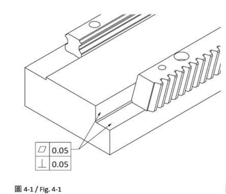 2. Prepare the following tools according to Figure 4-2, and carefully read the tool usage instructions in Table 4-1.
| No | Tool | Purpose |
| 1 | Hex-socket bolt | To tighten the rack to the frame. |
| 2 | Positioning pin | To fasten the rack to the frame. |
| 3 | Over pin | A part used to convenient'y check the accuracy of rack connection. |
| 4 | Dial gauge | To inspect the accuracy of rack connection |
| 5 | Sharpening stone | To clean related installation equipment. |
| 6 | Magnet | To induce magnetic properties in over-pin. |
| 7 | Torque wrench | To tighten bolts. |
| 8 | Rubber hammer | To slightly adjust the installation position of rack. |
| 9 | Cleaning agent | To clean related installation equipment. |
| 10 | C clamp | Used to quickly fasten he rack when assembling. |
| 11 | Gauge | To fast align connecting positon between two racks. |
3. Wear protective gloves and work shoes only under the circumstance that there is no risk of entrapment.
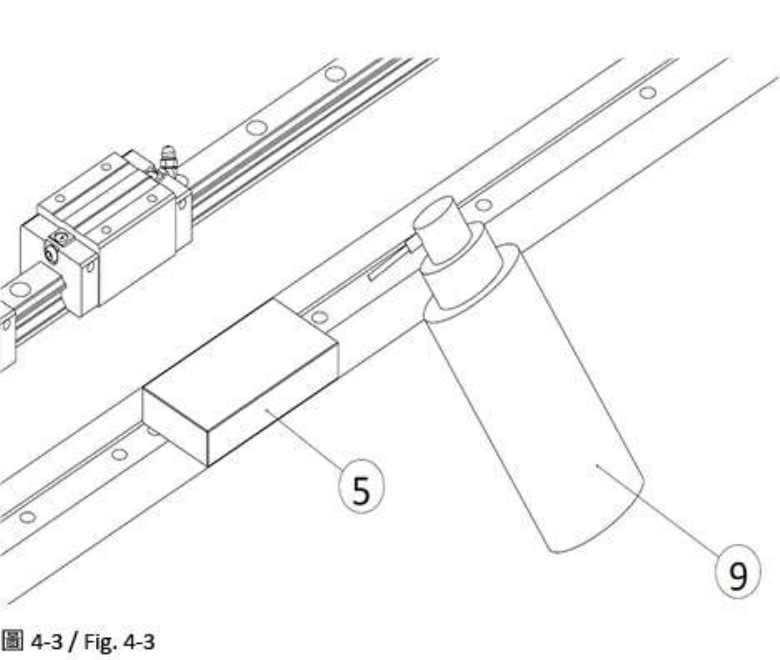
4. Use a cleaning agent that will not cause rust or corrosion to accessories to clean the installation surface, as shown in Figure 4-3.
5. Clean the contact and supporting surfaces with a sharpening stone and a clean rag, as shown in Figure 4-3.
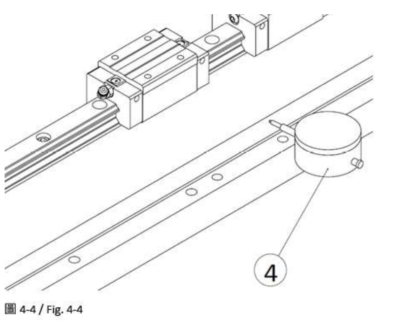
6. Use a dial gauge to check the parallelism between the contact and supporting surfaces and the linear guideway, as shown in Figure 4-4.
7. Place the rack nearby in advance to adapt to the surrounding temperature.
Note: When using the dial indicator, please fix its bracket on the slider before testing.
V. Mounting Instructions
1. Place a rack in the center of the frame. In order to prevent the rack from continuously accumulating pitch errors and hole deviations during installation, it is recommended that the user commence installation with middle position as the basis to minimize the error.
2. Use a C clamp to fix the rack to the bolt screw-on position, as shown in Figure 4-5.
To ensure that the teeth will not be damaged due to clamping, it is recommended that the user pad it with soft material, or to ensure that the chuck material will not damage the teeth.
3. Insert the hex-socket bolt and tighten it slightly. Commence tightening from the center hole of the rack. For the tightening torque of the bolts, refer to Table 5-1.
4. Tighten each bolt and remove the C clamp.
5. Place the racks to be connected to adjacent positions, and place the gauge between the connecting positions for preliminary positioning, as shown in Figure 4-6.
6. Use a C clamp to fasten the gauge on the frame.
7. Insert the bolt into the hole closest to the connecting position and tighten the bolt with a force close to half of the maximum tightening torque.
8. Tighten all bolts to the rack and frame according to the above method.
9. Release the C clamp and remove the gauge.
10. Use a magnet to induce magnetic properties in the over-pin.
11. Place three over-pins in the joints and the tooth gaps on both sides, as shown in Figure 4-7.
12. Use a dial indicator to measure the height difference between the first and third over-pin.
13. Determine whether the height difference between the first and third over-pins is within the tolerance range. This tolerance is defined within 10um-30um according to requirements, and will change depending on the rack module and stability requirements.
14. Measure the height difference of the second over-pin. If it is within the tolerance range, repeat steps 2-4 to complete the assembly.
15. If the height difference across the over-pin does not meet the tolerance requirements, use a rubber hammer to tap lightly on both ends of the rack, or to use a fine-adjustable device to adjust.
16. Depending on the number of connecting racks, repeat steps 5-15 to accomplish the assembly.
Note: If the rack must be fully positioned, please see Section 6 “Final Inspection”.
VI. Final Inspection
1. In order to ensure the parallelism of the overall movement stroke, place the over-pin rods in the tooth gaps. It is recommended to place an overpin every 200mm, as shown in Figure 6-1.
2. Use a dial indicator to measure the height difference of each over-pin and record it.
3. Determine whether the maximum height difference is within the tolerance range. This tolerance is defined within 10um-30um according to requirements, and it will change depending on the rack module and stability requirements.
4. Use a C clamp to fix it to the frame at the positioning hole, as shown in Figure 6-2.
5. Use a screw tap to tap the positioning holes of the rack and frame to a size suitable for the positioning pins.
6. Clean the iron filings to avoid affecting the assembly.
7. Install the positioning pin to accomplish the positioning.


Login and Registration Form